


Ambiq Micro Apollo Mini-EVB Development Board
$59.95
Product Description
Contents
Overview
This is a development board based on Ambiq Micro’s Ultra-Low Power Apollo MCU. The Apollo MCU family is an ultra-low power, highly integrated microcontroller designed for batterypowered devices including wearable electronics, activity & fitness monitors, and wireless sensors. By combining ultra-low power sensor conversion electronics with the powerful ARM Cortex-M4F processor, the Apollo MCU enables complex sensor processing tasks to be completed with unprecedented battery life. Weeks, months, and years of battery life are achievable while doing complex context detection, gesture recognition, and
activity monitoring. The Apollo MCU takes full advantage of Ambiq Micro’s patented Subthreshold Power Optimized Technology (SPOT) Platform, setting a new industry benchmark in low power design.
The Apollo MCU also integrates up to 512 KB of flash memory and 64 KB of RAM to accommodate radio and sensor overhead while still leaving plenty of space for application code. This microcontroller also includes a serial master and UART port for communicating with radios and sensors including accelerometers, gyroscopes, and magnetometers.
The SPOT Platform reduces the current consumption of this MCU to only 35uA/MHz@3.3V and 143nA@3.3 V in deep sleep mode. As this MCU is commonly used in batterypowered devices, power consumption measurement one of the most important tasks in development. When the MCU switches between active mode and deep sleep mode, which is the most common case, measuring the power consumption (current) can be a big challenge for mid-end digital multimeters:
- When mA/A is selected on the multimeter, the current in deep sleep mode is too small to be measured.
- When uA is selected on the multimeter, the MCU switches back to active mode, the measuring range overruns and the power to the MCU drops too much because of the sensing resistor in the multimeter, which causes reset or brown out.
What makes things worse is that, with low voltage application, the burden voltage of the digital multimeter is not negligible any more. To overcome this issue, some sophisticated circuit is added to the board.
- The voltage applied to the MCU (VDD) is fed back to the LDO. The LDO will adjust its power output so that the MCU gets a stable voltage (selected by a potential meter.).
- The current is converted to voltage so that the power consumption can be measured by a digital multimeter or visualized/analysed on a oscilloscope.
- The power consumption of some other components can be optionally taken into account by connecting to different power buses.
Features
- Ultra-Low Power
- EEMBC ULPBench score of 377
- 35 µA/MHz executing from flash at 3.3 V
- 143 nA deep sleep mode at 3.3 V
- 419 nA deep sleep mode with XTAL-assisted RTC at 3.3 V
- High-performance ARM Cortex-M4F Processor (up to 24 MHz clock frequency)
- Floating point unit
- Up to 512 KB of flash memory for code/data
- Up to 64 KB of low leakage RAM for code/data
- Current sensing circuit with voltage output
- LED indicators for events such as over current, over temperature, over range etc.
Some details
There are two power rails named VDD and VTRACK, implemented with two LDOs and additional circuits in the feedback loop. VDD is in the range of 2.1-3.3V and can be selected with RP1 knob. VTRACK tracks the voltage of VDD and there is a small offset voltage which could be set via R4. It is recommended to set VTRACK 10mV less than VDD.
Due the additional current measurement circuit in the feedback loop of the LDO, to ensure that the two power rails work as expected during power on period, both LDOs are shut down by MAX811 during power on circuit. When VBUS goes higher than 4.38V, the LDOs are enabled. If the voltage of VBUS goes lower than 4.38V, both LDO will be shut down for at least 140ms.
Current Measurement
The current measurement is done on VDD which powers the MCU . Onboard LEDs, buttons, and external peripherals/debugger are powered by VDEBUG. VDEBUG could be selected to connect to VDD or VTRACK by jumper.
The I-V current measurement is divided into three ranges, which measures the current consumptions of everything connected to VDD.
- nA: 2.5nA-3500nA with output voltage of 1mV/nA
- uA: 2.5uA-3500uA with output voltage of 1mV/uA
- mA:0.25mA-350mA with output voltage of 10mV/mA
As the circuits generate VTRACK needs to sense the VDD to follow the change of it, there is a ~70nA bias current which adds to the I-V result, and the leakage via the substrate of the PCB and surface will also contribute to the I-V result, which means the I-V result will not be zero even if the MCU have consumed no current.
User could select the range of the measurement via jumper P7 and if the jumper is disconnected or current measurement is over/under range from P7 the load on VDD will not be powered down.
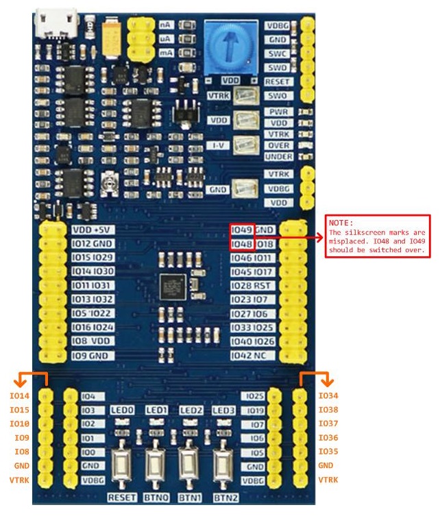
Pinout
LEDs
- Power (Green) – Power indicator
- VDD (Red) – VDD LDO error, over current, over temperature, etc.
- VTRACK (Red) – VTRACK LDO error, over current, over temperature, etc.
- OVER (Orange) – Current measurement over range
- UNDER (Blue) – Current measurement under range
In the Package
- Ambiq Micro Apollo Mini-EVB Development Board
- Micro USB cable


Reviews
There are no reviews yet.