Contents
Overview
This sensor module has an MG-811 onboard as the sensor component. There is an onboard signal conditioning circuit for amplifying output signal and an onboard heating circuit for heating the sensor. The MG-811 is highly sensitive to CO2 and less sensitive to alcohol and CO. It could be used in air quality control, ferment process, in-door air monitoring application. The output voltage of the module falls as the concentration of the CO2 increases.
Features
- Analog and digital output
- Onboard signal conditioning circuit
- Onboard heating circuit
- Sensor jack eliminates soldering the sensor and allows plug-and-play
- 4-pin interlock connectors onboard
- 4-pin interlock cables included in the package
- Compact size
MG-811 Specifications
| Symbol | Parameter | Value | Remarks |
|---|---|---|---|
| VH | Heating Voltage | 6.0±0.1V | AC or DC |
| RH | Heating Resistor | ~30.0 Ohm | At room temperature |
| IH | Heating Current | ~200mA | |
| PH | Heating Power | ~1200mW | |
| Tao | Operating Temperature | -20 – 50°C | |
| Tas | Storage Temperature | -20 – 70°C | |
| EMF | Output | 100-600mV | 400-10000ppm CO2 |
Pinout
| Pin | Description | Remarks |
|---|---|---|
| VCC | 5V power supply for signal conditioning | <5.5V |
| VOUT | Analog voltage signal output | |
| BOOL | Comparator output | Open drain |
| HEAT | Heating power supply | |
| VSET | Heating voltage select | 0-5V |
| GND | Common ground | Onboard heating circuit |
*Please note that the heating voltage should be 7.5-12V instead of 6-24V as marked around the barrel connector on the PCB.
Test Points
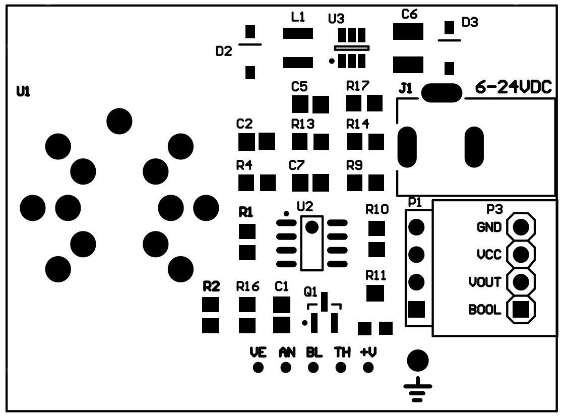
There are six test points on board. They are VE, AN, BL, TH, +V and GND.
| VE | the regulated heating voltage, typical values are 6.0V |
| AN | analog output, the voltage should drop down when CO2 concentration rises |
| BL | digital output, see “Comparator” Section above |
| TH | comparator threshold voltage, you can set it to any value between 0 and +V |
| +V | signal conditioning circuit power supply, which is 5V |
Typical Application Schematics

Theory
The MG-811 sensor is basically a cell which gives an output in the range of 100-600mV (400—10000ppm CO2). The current sourcing capability of the cell is quite limited. The amplitude of the signal is so low and the output impedance of the cell is so high that a signal conditioning circuit is required between the sensor and microcontroller’s ADC input. The output voltage of the sensor in clean air (typically 400ppm CO2) is in the range of 200mV-600mV, this output voltage is defined as Zero Point Voltage (V0) which is the baseline voltage. The output voltage will decrease as the CO2 concentration increases. When the concentration of CO2 is greater than 400ppm, the output voltage (Vs) is linear to the common logarithm of the CO2 concentration (CCO2):
Vs = V0 +ΔVs / (log10400 – log101000) * (log10CCO2 – log10400)
WhereΔVs = sensor output@400ppm – sensor output@1000ppm
Reaction Voltage(ΔVs) is the voltage drop from CO2 concentration of 400ppm to CO2 concentration of 1000ppm, which may differ from sensor to sensor. The typical value forΔVs is 30mV-90mV. In order to get an accurate CO2 concentration result, proper calibration is required.
The DC gain of the signal conditioning circuit is 8.5. So the range of VOUT is 0.85-5.0V, which is a reasonable range for a 5V microcontroller or standalone ADC.
The threshold of the comparator open drain output pin BOOL can be set by on-board trimmer R11. When VOUT is lower than the threshold voltage the BOOL is at ground potential. When VOUT is greater than the preset value, the BOOL is open circuit. User should connect a pull-up resistor to the BOOL pin in order to have a valid “high” state.
Signal Conditioning Circuit
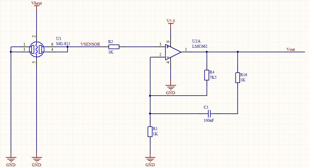
The LMC662 is used as the amplifier because of its ultra high input impedance. According to the datasheet of MG-811, this sensor require an input impedance of 100-1000Gohm, the LMC662 has an input resistance above 1Tohm, which meets this requirement. The typical input offset voltage of this OPA is about 3mV, which is insignificant for this application. The DC gain is set by R4 and R1, with the formula
Vout = Vin * (1 + R4/R1)
In this specific application, Vout = 8.5*Vin.
R16 and C1 form a Low Pass Filter which gives a cleaner output by filtering out the high frequency noise.
Comparator Circuit
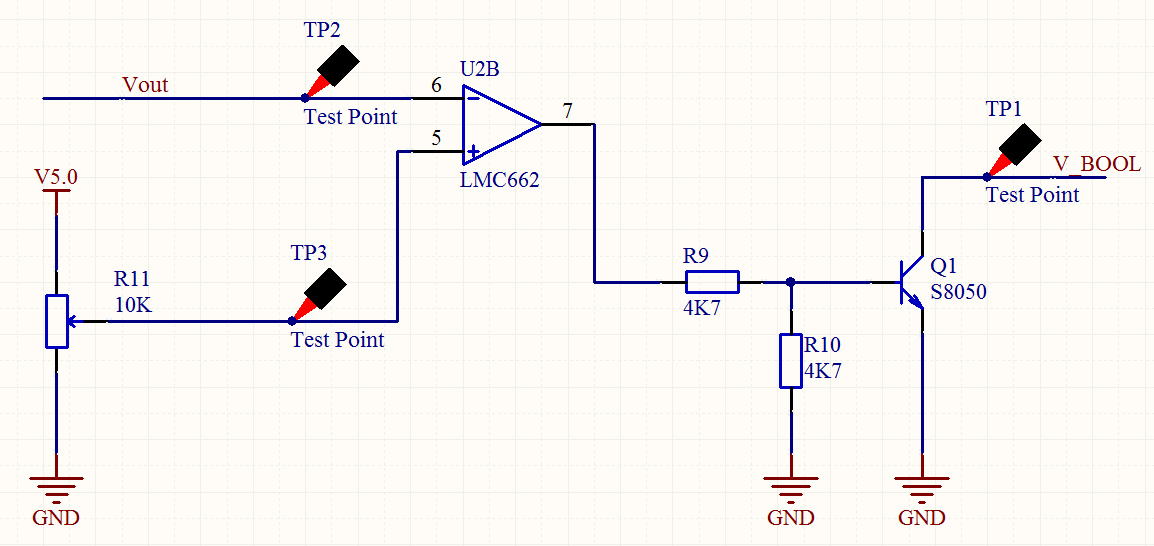
The LMC662 is used as a comparator here. The R11 set the threshold of the comparator. If VOUT goes below the threshold, V_BOOL is at ground potential. If VOUT goes greater than the threshold, V_BOOL is floating. A pull-up resistor is needed to pull the BOOL pin up in order to have a valid “high” state when V_BOOL is floating.
Switch Mode Regulator Circuit

This is a typical step-down SMPS, the feedback voltage of the MP2359 is 0.81V, here is the relationship between VIN and VOUT of this circuit. This is not a low power device, so please don’t use a 9V battery as the power source of the heating circuit. The battery will die very soon if you apply it to this circuit.
VOUT = 0.81 * (1 + R13/R14)
In this specific application, VOUT = 0.81 * (1 + 10.2K/1.58K) = 6.0V
Sample Code for Arduino
|
1 2 3 4 5 6 7 8 9 10 11 12 13 14 15 16 17 18 19 20 21 22 23 24 25 26 27 28 29 30 31 32 33 34 35 36 37 38 39 40 41 42 43 44 45 46 47 48 49 50 51 52 53 54 55 56 57 58 59 60 61 62 63 64 65 66 67 68 69 70 71 72 73 74 75 76 77 78 79 80 81 82 83 84 85 86 87 88 89 90 91 92 93 94 95 96 97 98 99 100 101 102 103 104 105 106 107 108 109 110 111 |
/*******************Demo for MG-811 Gas Sensor Module V1.1***************************** Author: Tiequan Shao: tiequan.shao@sandboxelectronics.com Peng Wei: peng.wei@sandboxelectronics.com Lisence: Attribution-NonCommercial-ShareAlike 3.0 Unported (CC BY-NC-SA 3.0) Note: This piece of source code is supposed to be used as a demostration ONLY. More sophisticated calibration is required for industrial field application. Sandbox Electronics 2012-05-31 ************************************************************************************/ /************************Hardware Related Macros************************************/ #define MG_PIN (0) //define which analog input channel you are going to use #define BOOL_PIN (2) #define DC_GAIN (8.5) //define the DC gain of amplifier /***********************Software Related Macros************************************/ #define READ_SAMPLE_INTERVAL (50) //define how many samples you are going to take in normal operation #define READ_SAMPLE_TIMES (5) //define the time interval(in milisecond) between each samples in //normal operation /**********************Application Related Macros**********************************/ //These two values differ from sensor to sensor. user should derermine this value. #define ZERO_POINT_VOLTAGE (0.220) //define the output of the sensor in volts when the concentration of CO2 is 400PPM #define REACTION_VOLTGAE (0.020) //define the voltage drop of the sensor when move the sensor from air into 1000ppm CO2 /*****************************Globals***********************************************/ float CO2Curve[3] = {2.602,ZERO_POINT_VOLTAGE,(REACTION_VOLTGAE/(2.602-3))}; //two points are taken from the curve. //with these two points, a line is formed which is //"approximately equivalent" to the original curve. //data format:{ x, y, slope}; point1: (lg400, 0.324), point2: (lg4000, 0.280) //slope = ( reaction voltage ) / (log400 –log1000) void setup() { Serial.begin(9600); //UART setup, baudrate = 9600bps pinMode(BOOL_PIN, INPUT); //set pin to input digitalWrite(BOOL_PIN, HIGH); //turn on pullup resistors Serial.print("MG-811 Demostration\n"); } void loop() { int percentage; float volts; volts = MGRead(MG_PIN); Serial.print( "SEN-00007:" ); Serial.print(volts); Serial.print( "V " ); percentage = MGGetPercentage(volts,CO2Curve); Serial.print("CO2:"); if (percentage == -1) { Serial.print( "<400" ); } else { Serial.print(percentage); } Serial.print( "ppm" ); Serial.print("\n"); if (digitalRead(BOOL_PIN) ){ Serial.print( "=====BOOL is HIGH======" ); } else { Serial.print( "=====BOOL is LOW======" ); } Serial.print("\n"); delay(200); } /***************************** MGRead ********************************************* Input: mg_pin - analog channel Output: output of SEN-000007 Remarks: This function reads the output of SEN-000007 ************************************************************************************/ float MGRead(int mg_pin) { int i; float v=0; for (i=0;i<READ_SAMPLE_TIMES;i++) { v += analogRead(mg_pin); delay(READ_SAMPLE_INTERVAL); } v = (v/READ_SAMPLE_TIMES) *5/1024 ; return v; } /***************************** MQGetPercentage ********************************** Input: volts - SEN-000007 output measured in volts pcurve - pointer to the curve of the target gas Output: ppm of the target gas Remarks: By using the slope and a point of the line. The x(logarithmic value of ppm) of the line could be derived if y(MG-811 output) is provided. As it is a logarithmic coordinate, power of 10 is used to convert the result to non-logarithmic value. ************************************************************************************/ int MGGetPercentage(float volts, float *pcurve) { if ((volts/DC_GAIN )>=ZERO_POINT_VOLTAGE) { return -1; } else { return pow(10, ((volts/DC_GAIN)-pcurve[1])/pcurve[2]+pcurve[0]); } } |
Resources
- MG-811 Datasheet
- LMC662 Datasheet
- MP2359 Datasheet
- A Great Guide wrote by Martin Liddament about Sensor Calibration, Display and Data Logging
- Another Great Guide wrote by Andrea Zamuner Cervi about Sensor Calibration, Display, Data Logging locally on SD card or online at EmonCMS (in Italian) and its Google translation
Demo Output
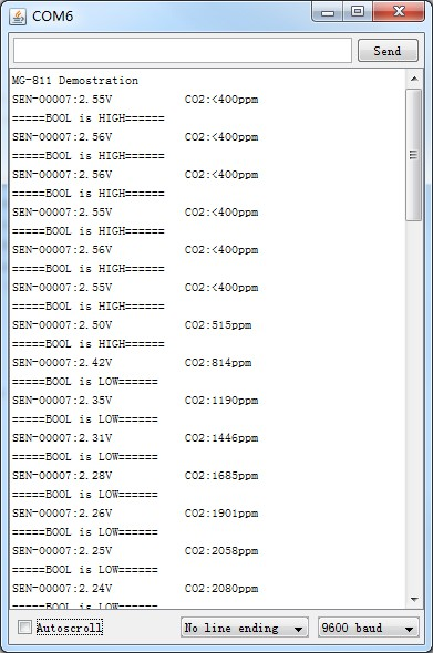
Demo output when a small amount of breath is puffed to the sensor.
Assembly Drawing
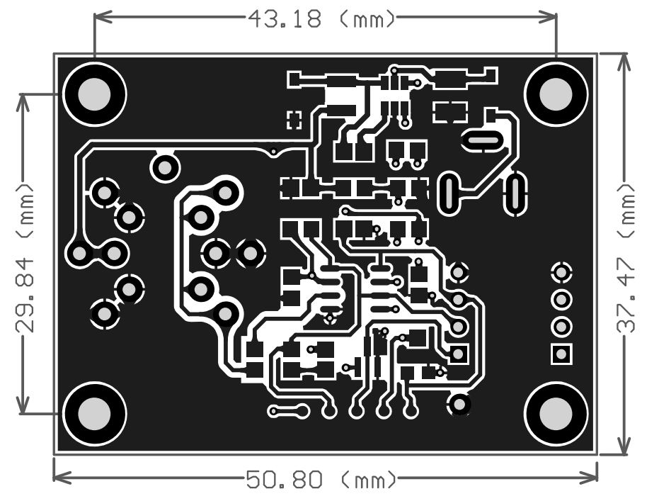
Dimensions
I have bought this product.
It is arrived yesterday from China.
It is very good.
And this page about datasheet + example is also very very good.
Thank you!
is there any way to use this sensor on the Teensy 3.1? Analog in is max 3.3v
You may need to modify the feedback resistor values to limit the output of the module to 0-3.3V. Also, the onboard amp op need 5v to operate, so please make sure that you have a 5V supply on Teensy 3.1.
Hi, I bought your sensor and wired it up. I have a question tho. Do I have to supply additional power to the sensor for the heating or the Arduino does that? Thank you
Yes, an external supply is mandatory.
Hello everybody,
I want to modify this circuit to connect it to a 3,3v device. To do that I’ve changed the op amp gain by changing R4 and R1 (in the Signal Conditioning Schematics chapter) but now I don’t know if I can leave the resistance (R16) and the cap (C1) unchanged. What is the aim of those component? Do they filter low frequencies? Can I leave them 1Kohm and 100nF?
Thanks for your help!
Hi Andrea,
Just leave the R16 and C1 unchanged. They offers a relative low impedance in the feedback loop to keep the noise low.
Kim
Is there any option how to power this module directly from Arduino Mega 2560, which is powered by 9V/1A adapter? I mean not only data, but heating also. Is it needed to power heating anyway? Or is there an option, – let’s say if operating temperature will be always between 20-35°C – not to power the heating?
1. Connect Vin of Arduino Mega to the inter polar of the barrel connector, and connect GND of Arduino Mega to the outer shell of the barrel connector.
2. Connect +5V of Arduino Mega to Vcc(red) of the module, and connect GND of Mega to GND(black) of the module.
i buy mg811 from sandbox electronics i have question ,should i connect this sensor to 3.3v or 5v from arduino?
please reply
thank you in advance
The VCC should be powered by 5V and the barrel connector should be powered by 9-12V.
Hello, can I power the external VE by 13.8V? The last post notes 6-12V. Thank you
All the modules are tested with 15V before shipping and the DC-DC chip has a input rating of 24V . It is OK if you connected with 13.8V.
I was wondering if there is an approximate resolution for this sensor for the range of 400-10,000 ppm? Can it be expected to provide accuracy of +/-1 ppm or would it be more like +/- 10 ppm?
The output of this sensor is analog voltage and if you are going to use it with a MCU. The resolution depends on the ADCs of your MCU. As for the accuracy, +-10ppm is quite hard to achieve.