Contents
Introduction
This Guide will walk you through the whole process of setting up a LoRaWAN gateway with a LoRaGo PORT kit and a Raspberry Pi 2/3. For multi-channel LoRaWAN gateway, LoRaGo PORT is a good alternative to the well-known IMST iC880a. The hardware is basically the same as iC880a except it is more compact in size. It has dedicated HAT for Raspberry 2/3 which makes the installation easy and neat. It works with any software that works with iC880a.
Hardware
- LoRaGo PORT board
- LoRaGo PORT HAT for Raspberry Pi
- U.FL to SMA Female pigtail cable
- Antenna
- Raspberry Pi 2/3 with MicroSD card
- 5V >=1.5A micro USB power supply for Raspberry Pi 2/3
- (Optional) GPS antenna
- (Optional) U.FL Female to U.FL Female cable for PPS signal
- (Optional) WiFi dongle
Preparing the RasPi
In theory, many of the OS variants should be OK. But we have only tested on Raspbian Jessie Desktop/Lite and Raspbian Stretch Desktop/Lite. For new installations, we would recommend Raspbian Stretch Lite. If you are comfortable with setting up the RasPi yourself, you could jump directly to the next section. You only need to make sure that SPI is enabled and the RasPi has an Internet connection.
Raspbian has very good instruction on installing the OS image. You could either follow the NOOBS way or the Etcher way.
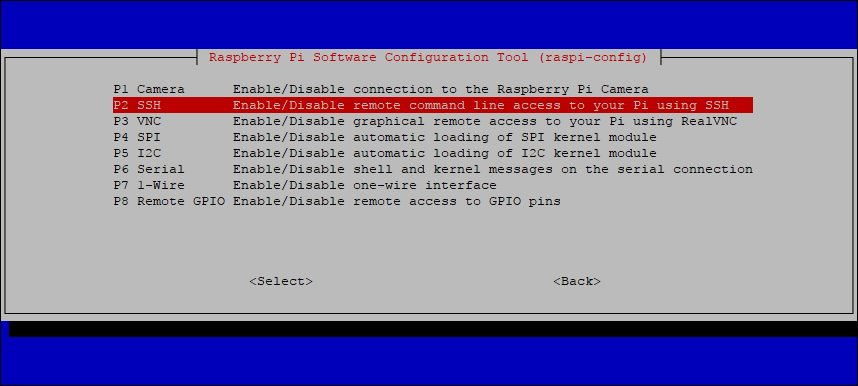
After fresh installation, SSH and SPI are disabled by default.
- SSH is not mandatory but is useful for remote access via terminal software such as PuTTY.
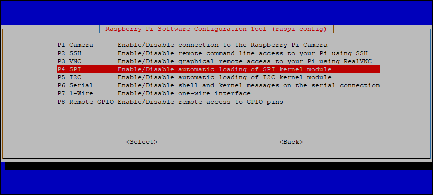
- SPI is mandatory because it is used to communicate with the LoRaGo PORT.
The classic way
Both SSH and SPI can be enabled by running
sudo raspi-config wizard if you are comfortable with connecting a monitor and a keyboard to the RasPi. (The default username and password is “pi” and “raspberry”)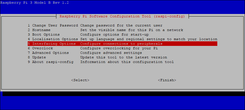
For older version of Raspbian, the SSH and SPI configuration are probably under “Advanced Options” instead of “Interfacing Options”.
The headless way
Sometimes, it is not very convenient to connect a monitor and a keyboard to the RasPi. There is some way to do it. It is out of the scope of this guide. This is how we did it with a Windows PC in brief:
- Insert the MicroSD card to a Windows PC
- Open the first partition of the MicroSD card labeled as boot (not the “/boot” directory)
- Create a new text file called “ssh” (without any file extension). Leave the content empty
- Safely remove the MicroSD card from the PC and insert it to the RasPi
- Connect the RasPi to the network with an Ethernet cable and power it on
- The RasPi should be accessible by hostname “raspberrypi.local”
- Start a terminal, ssh to raspberrypi.local and make necessary configuration
After setting up the Raspi by the headless way, enable the SPI interface by running sudo raspi-config command (the procedure is the same as the classic way).
Configuring WiFi
If WiFi is the choice of connection instead of Ethernet, the WiFi credentials need to be configured. Open the configuration file with nano.
|
1 |
sudo nano /etc/wpa_supplicant/wpa_supplicant.conf |
Add the WiFi credentials to the end of the file.
|
1 2 3 4 |
network={ ssid="SSID" psk="PASSWORD" } |
Save the file by pressing Ctrl+X, then Y, then finally press Enter.
Reconfigure the interface
|
1 |
wpa_cli -i wlan0 reconfigure |
You can verify whether it has successfully connected using ifconfig wlan0 . If the inet addr field has an address beside it, the Raspberry Pi has connected to the network. If not, check that your SSID and password are correct.
Setting up the hardware
- Install the LoRaGo PORT board onto the LoRaGo PORT HAT
- Install the LoRaGo PORT HAT onto the RasPi
- Connect the Antenna to the end of the pigtail
- Connect the pigtail to the U.FL connector marked as “RF” on the LoRaGo PORT board
- (Optional) Connect the GPS antenna
- (Optional) Connect the PPS output from the HAT to the PPS input on the LoRaGo PORT board.
- Power up the RasPi
The setup should look like this: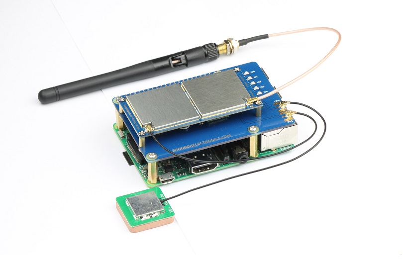
Installing the software
Install git.
|
1 2 3 |
sudo apt-get update sudo apt-get upgrade sudo apt-get install git |
Clone the installer from github.
|
1 |
git clone https://github.com/ttn-zh/ic880a-gateway.git ~/ic880a-gateway |
Run the installation script.
|
1 2 |
cd ~/ic880a-gateway sudo ./install.sh spi |
Important note:
- Please DO NOT forget the “spi” parameter!!! (We have received more than 20 support cases because of the missing “spi” parameter. Without this parameter, a wrong branch of source code will be installed.)
- The install.sh script will ask for some inputs. When it asks “Do you want to use remote settings file? [y/N]”, select “N” if you don’t know what this option means. Selecting “y” will require extra steps to get the gateway running. For more information about remote setting: https://github.com/ttn-zh/gateway-remote-config
- The installation uses EU region global_conf.json by default. If you use the gateway in other regions, please replace /opt/ttn-gateway/bin/global_conf.json with the one of these after the installation. The file name always has to be global_conf.json (without the region prefix). The related frequency settings in the global_conf.json define the frequency the gateway operates with. (The RF circuit of the LoRaGo PORT is tuned to operate with the best performance for the target band. That is why there are different hardware for the different region)
- The installation script creates a service (ttn-gateway.service) that starts the gateway process (/opt/ttn-gateway/bin/start.sh and /opt/ttn-gateway/bin/poly_pkt_fwd) automatically on reboots. There is no need to run any command manually. Running extra process would probably lead to error conditions.
Registering the gateway with TTN
1. Create an account at https://account.thethingsnetwork.org/register
2. Navigate to the Console.
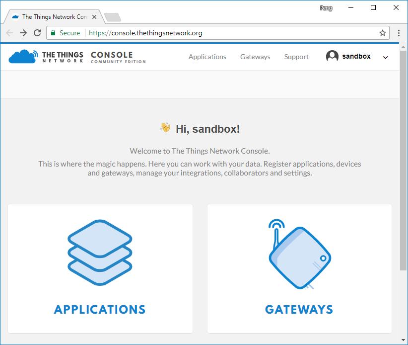
3. Click GATEWAYS.
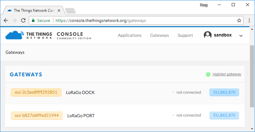
4. Click register gateway
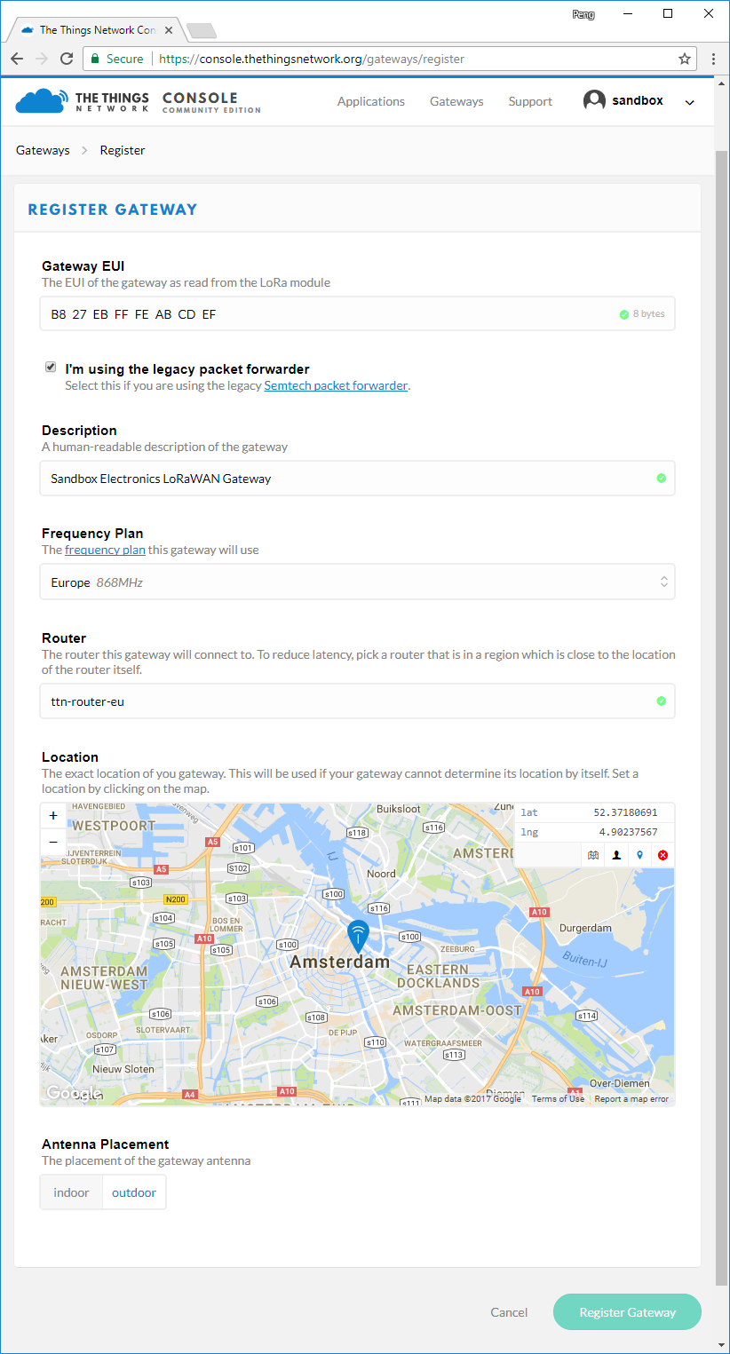
5. Fill in the information as above.
- Check the checkbox “I’m using the legacy packet forwarder”
- The “Gateway EUI” field should be filled with 8 byte in Hex format. You could get the Gateway EUI from the RasPi shell with command
1cat /opt/ttn-gateway/bin/local_conf.json | grep gateway_ID - Select the frequency plan according to local regulation.
- Select the closest router
- Mark the location of the gateway on the map
- Select Antenna Placement as indoor or outdoor
- Click “Register Gateway”
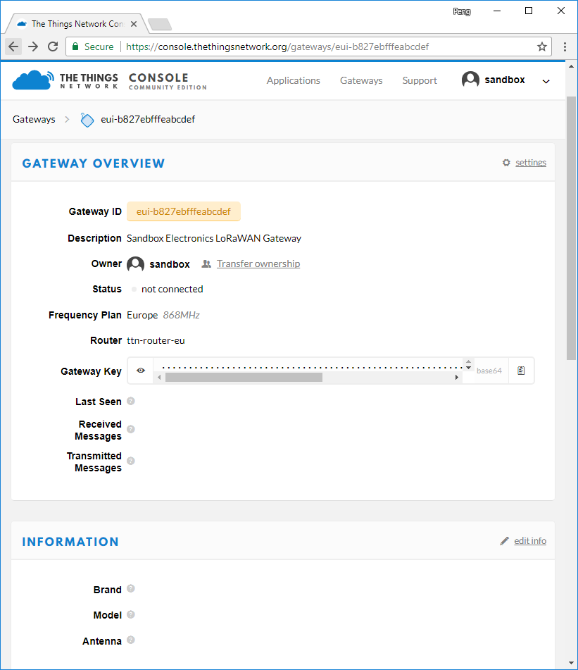
6. In the Gateway Overview page, click “edit info”.
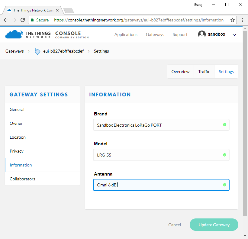
Fill in the Brand, Model and Antenna with appropriate information. Click “Update Gateway”. We are all set.
Extra: Configurations for US-915 Band and Others
The instructions and setup above are for 868MHz Band. To use US-915 band, some changes have to be made:
- Replace /opt/ttn-gateway/bin/global_conf.json with this. (For other regions, please use one of these)
- Change “server_address” in /opt/ttn-gateway/bin/local_conf.json to router.us.thethings.network. (For other regions, please select the closest one from here).
- Select “United State 915MHz” as frequency plan in TTN Console->Gateway Settings->General
- Select the closest router (ttn-router-us-west) in TTN Console->Gateway Settings->General
Extra: Using the onboard GPS data as gateway location
The installation package uses “fake_gps” by default. This means that the program will ignore the GPS data received from the onboard GPS module. In order to use “real” GPS, one line "fake_gps": false, should be added to the /opt/ttn-gateway/bin/local_conf.json file in order to override the default setting in the global_conf.json file. The result should look like this:
|
1 2 3 4 5 6 7 8 9 10 11 12 |
{ "gateway_conf": { "gateway_ID": "B827EBFFFEEB487F", "servers": [ { "server_address": "router.eu.thethings.network", "serv_port_up": 1700, "serv_port_down": 1700, "serv_enabled": true } ], "fake_gps": false, "ref_latitude": 0, "ref_longitude": 0, "ref_altitude": 0, "contact_email": "", "description": "ttn-ic880a" } } |
Extra: Fixing the serial port (uart) issue on RasPi 3
WiFi and Bluetooth hardware are added to RasPi 3 and RasPi Zero W. New issues are introduced at the same time. The bluetooth hardware takes /dev/ttyAMA0 from the system which was used as a general UART interface on the GPIO header on RasPi “pre-3”. The TTN source code we use above still try to use /dev/ttyAMA0 to get GPS data. This obviously will not work. One way to fix this is to disable bluetooth and return /dev/ttyAMA0 to general UART interface:
- run sudo raspi-config, go to Interfacing Options->Serial
- Choose <No> for “Would you like a login shell to be accessible over serial?”
- Choose <Yes> for “Would you like the serial port hardware to be enabled?”
- Exit raspi-config
- Add a line at the end of /boot/config.txt: dtoverlay=pi3-disable-bt
- Reboot the RasPi. The general UART interface should now be accessible via /dev/ttyAMA0
For more detail about the serial port on RasPi 3, refer to this blog page.
I just created and published a 3D printable housing for a Raspbery Pi together with the gateway. Maybe you want to add it to your article: https://www.thingiverse.com/thing:2843380
Thank you so much ^_^