Overview
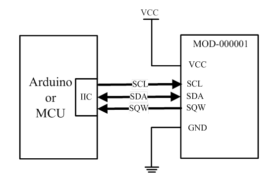
This module has a DS1307, a battery socket and three pull-up resistors on the PCB. It uses I2C protocol to communicate with external I2C master (Arduino board, PIC, AVR, etc.). The SQW/OUT pin of DS1307 is broke out via a 3-pin interlock connecter. A 4-pin connector eases the wiring to an Arduino Sensor Shield. The three pull-up resistors are connected to SDA, SCL, and SQW respectively, and they are clearly noted on the silkscreen of the PCB. User could take them off board if those pull-up resistors have already been implemented somewhere else off the module.
Features
- Onboard battery socket (CR2032 battery included)
- 3-pin and 4-pin interlock connectors
Typical Application Diagram
Arduino Sample Code
DS1307 Library should be downloaded and included as shown in the source code.
|
1 2 3 4 5 6 7 8 9 10 11 12 13 14 15 16 17 18 19 20 21 22 23 24 25 26 27 28 29 30 31 32 33 34 35 36 37 |
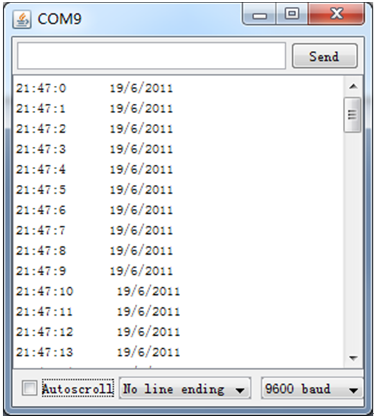
#include <WProgram.h> #include <Wire.h> #include <DS1307.h> // written by mattt on the Arduino forum and modified by D. Sjunnesson void setup() { Serial.begin(9600); RTC.stop(); RTC.set(DS1307_SEC,1); //set the seconds RTC.set(DS1307_MIN,47); //set the minutes RTC.set(DS1307_HR,21); //set the hours RTC.set(DS1307_DOW,7); //set the day of the week RTC.set(DS1307_DATE,19); //set the date RTC.set(DS1307_MTH,6); //set the month RTC.set(DS1307_YR,11); //set the year RTC.start(); } void loop() { Serial.print(RTC.get(DS1307_HR,true)); //read the hour and also update all the values by //pushing in true Serial.print(":"); Serial.print(RTC.get(DS1307_MIN,false)); //read minutes without update (false) Serial.print(":"); Serial.print(RTC.get(DS1307_SEC,false)); //read seconds Serial.print(" "); // some space for a more happy life Serial.print(RTC.get(DS1307_DATE,false));//read date Serial.print("/"); Serial.print(RTC.get(DS1307_MTH,false)); //read month Serial.print("/"); Serial.print(RTC.get(DS1307_YR,false)); //read year Serial.println(); delay(1000); } |
Demo Output