Contents
Overview
This sensor module utilizes an MQ-6 as the sensitive component and has a protection resistor and an adjustable resistor on board. The MQ-6 gas sensor is highly sensitive to LPG, iso-butane, propane and less sensitive to alcohol, cooking fume and cigarette smoke. It could be used in gas leakage detecting equipments in family and industry. The resistance of the sensitive component changes as the concentration of the target gas changes.
Features
- Continuous Analog output
- 3-pin interlock connector
- Low cost and compact size
Standard Working Condition
| Symbol | Parameter Name | Technical Condition | Remarks |
| VC | Circuit voltage | 5V±0.1 | AC or DC |
| VH | Heating voltage | 5V±0.1 | AC or DC |
| RL | Load resistance | 20Kohm | |
| RH | Heater resistance | 33Kohm±5% | Room temperature |
| PH | Heating consumption | Less than 750mW |
Environment Condition
| Symbol | Parameter Name | Technical Condition | Remarks |
| TO | Operating Temp. | -10°C-50°C | |
| TS | Storage Temp. | -20°C-70°C | |
| RH | Relative Humidity | <95% | |
| O2 | Oxygen Concentration | 21%(standard condition) Oxygen concentration can affect sensitivity | Minimum value is 2% |
Sensitivity Characteristics
| Symbol | Parameter Name | Technical Condition | Remarks |
| RS | Sensor Resistance | 10Kohm-60Kohm (1000ppm LPG) | Detecting Concentration Scope: 200-10000ppm LPG, iso-butane, propane, LNG |
| α (1000ppm/4000ppm LPG) | Concentration slope rate | ≤0.6 | |
| Standard detecting Condition | Temp.: 20°C±2°C VC: 5V±0.1 Humidity:65%±5% VH:5V±0.1 |
||
| Preheating Time | Over 24 hours | ||
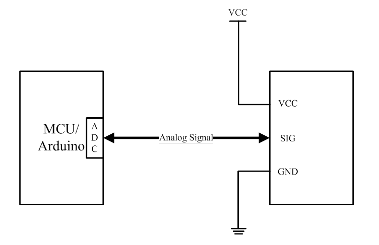
Typical Application Schematics
Theory
The protection resistor (10Kohms) and the adjustable (0-50Kohms) are in serial which forms a load resistor RL (10-60Kohms). The sensor’s resistance RS and RL forms a voltage divider. The output voltage on the signal pin could be read by Arduino or MCU via ADC. Given a value of RL, Power Supply Voltage, and output voltage, RS could be derived. Based on the chart provided in the MQ-6 datasheet, RS in clean air under given temperature and humidity is a constant, which is the “initial” resistance of the sensor named RO. RO of the resistor could be derived from RS. The main job of the calibration is to calculate the RO by sampling and averaging the readings when the module is placed in the clean air. Once the RO is derived, the concentration of target gas could be calculated by using the RS/RO ratio as the input. To achieve more accuracy, a segmented look-up table should be used. However, in the demonstration, a linear formula is used as an approximation to the original curve.
Arduino Sample Code
|
1 2 3 4 5 6 7 8 9 10 11 12 13 14 15 16 17 18 19 20 21 22 23 24 25 26 27 28 29 30 31 32 33 34 35 36 37 38 39 40 41 42 43 44 45 46 47 48 49 50 51 52 53 54 55 56 57 58 59 60 61 62 63 64 65 66 67 68 69 70 71 72 73 74 75 76 77 78 79 80 81 82 83 84 85 86 87 88 89 90 91 92 93 94 95 96 97 98 99 100 101 102 103 104 105 106 107 108 109 110 111 112 113 114 115 116 117 118 119 120 121 122 123 124 125 126 127 128 129 130 131 132 133 134 135 136 137 138 139 140 141 142 143 144 145 146 147 148 149 150 151 152 153 154 155 156 |
/*******************Demo for MQ-6 Gas Sensor Module V1.3***************************** Contact: support[at]sandboxelectronics.com Lisence: Attribution-NonCommercial-ShareAlike 3.0 Unported (CC BY-NC-SA 3.0) Note: This piece of source code is supposed to be used as a demostration ONLY. More sophisticated calibration is required for industrial field application. Sandbox Electronics 2014-02-03 ************************************************************************************/ /************************Hardware Related Macros************************************/ #define MQ_PIN (0) //define which analog input channel you are going to use #define RL_VALUE (20) //define the load resistance on the board, in kilo ohms #define RO_CLEAN_AIR_FACTOR (10) //RO_CLEAR_AIR_FACTOR=(Sensor resistance in clean air)/RO, //which is derived from the chart in datasheet /***********************Software Related Macros************************************/ #define CALIBARAION_SAMPLE_TIMES (50) //define how many samples you are going to take in the calibration phase #define CALIBRATION_SAMPLE_INTERVAL (500) //define the time interal(in milisecond) between each samples in the //cablibration phase #define READ_SAMPLE_INTERVAL (50) //define how many samples you are going to take in normal operation #define READ_SAMPLE_TIMES (5) //define the time interal(in milisecond) between each samples in //normal operation /**********************Application Related Macros**********************************/ #define GAS_LPG (0) #define GAS_CH4 (1) /*****************************Globals***********************************************/ float LPGCurve[3] = {3, 0, -0.4}; //two points are taken from the curve. //with these two points, a line is formed which is "approximately equivalent" //to the original curve. //data format:{ x, y, slope}; point1: (lg1000, lg1), point2: (lg10000, lg0.4) float CH4Curve[3] = {3.3, 0, -0.38}; //two points are taken from the curve. //with these two points, a line is formed which is "approximately equivalent" //to the original curve. //data format:{ x, y, slope}; point1: (lg2000, lg1), point2: (lg5000, lg0.7) float Ro = 10; //Ro is initialized to 10 kilo ohms void setup() { Serial.begin(9600); //UART setup, baudrate = 9600bps Serial.print("Calibrating...\n"); Ro = MQCalibration(MQ_PIN); //Calibrating the sensor. Please make sure the sensor is in clean air //when you perform the calibration Serial.print("Calibration is done...\n"); Serial.print("Ro="); Serial.print(Ro); Serial.print("kohm"); Serial.print("\n"); } void loop() { Serial.print("LPG:"); Serial.print(MQGetGasPercentage(MQRead(MQ_PIN)/Ro,GAS_LPG) ); Serial.print( "ppm" ); Serial.print(" "); Serial.print("CH4::"); Serial.print(MQGetGasPercentage(MQRead(MQ_PIN)/Ro,GAS_CH4) ); Serial.print( "ppm" ); Serial.print("\n"); delay(200); } /****************** MQResistanceCalculation **************************************** Input: raw_adc - raw value read from adc, which represents the voltage Output: the calculated sensor resistance Remarks: The sensor and the load resistor forms a voltage divider. Given the voltage across the load resistor and its resistance, the resistance of the sensor could be derived. ************************************************************************************/ float MQResistanceCalculation(int raw_adc) { return ( ((float)RL_VALUE*(1023-raw_adc)/raw_adc)); } /***************************** MQCalibration **************************************** Input: mq_pin - analog channel Output: Ro of the sensor Remarks: This function assumes that the sensor is in clean air. It use MQResistanceCalculation to calculates the sensor resistance in clean air and then divides it with RO_CLEAN_AIR_FACTOR. RO_CLEAN_AIR_FACTOR is about 10, which differs slightly between different sensors. ************************************************************************************/ float MQCalibration(int mq_pin) { int i; float val=0; for (i=0;i<CALIBARAION_SAMPLE_TIMES;i++) { //take multiple samples val += MQResistanceCalculation(analogRead(mq_pin)); delay(CALIBRATION_SAMPLE_INTERVAL); } val = val/CALIBARAION_SAMPLE_TIMES; //calculate the average value val = val/RO_CLEAN_AIR_FACTOR; //divided by RO_CLEAN_AIR_FACTOR yields the Ro //according to the chart in the datasheet return val; } /***************************** MQRead ********************************************* Input: mq_pin - analog channel Output: Rs of the sensor Remarks: This function use MQResistanceCalculation to caculate the sensor resistenc (Rs). The Rs changes as the sensor is in the different consentration of the target gas. The sample times and the time interval between samples could be configured by changing the definition of the macros. ************************************************************************************/ float MQRead(int mq_pin) { int i; float rs=0; for (i=0;i<READ_SAMPLE_TIMES;i++) { rs += MQResistanceCalculation(analogRead(mq_pin)); delay(READ_SAMPLE_INTERVAL); } rs = rs/READ_SAMPLE_TIMES; return rs; } /***************************** MQGetGasPercentage ********************************** Input: rs_ro_ratio - Rs divided by Ro gas_id - target gas type Output: ppm of the target gas Remarks: This function passes different curves to the MQGetPercentage function which calculates the ppm (parts per million) of the target gas. ************************************************************************************/ int MQGetGasPercentage(float rs_ro_ratio, int gas_id) { if ( gas_id == GAS_LPG ) { return MQGetPercentage(rs_ro_ratio,LPGCurve); } else if ( gas_id == GAS_CH4 ) { return MQGetPercentage(rs_ro_ratio,CH4Curve); } return 0; } /***************************** MQGetPercentage ********************************** Input: rs_ro_ratio - Rs divided by Ro pcurve - pointer to the curve of the target gas Output: ppm of the target gas Remarks: By using the slope and a point of the line. The x(logarithmic value of ppm) of the line could be derived if y(rs_ro_ratio) is provided. As it is a logarithmic coordinate, power of 10 is used to convert the result to non-logarithmic value. ************************************************************************************/ int MQGetPercentage(float rs_ro_ratio, float *pcurve) { return (pow(10, (((log(rs_ro_ratio)-pcurve[1])/pcurve[2]) + pcurve[0]))); } |
Demo Output
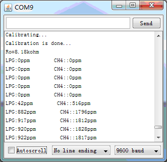 Demo output as an extinguished cigarette lighter approaches
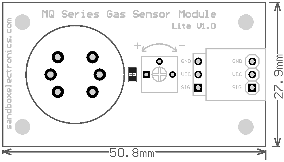
Dimensions