Contents
Overview
This breadboard power supply features in a dual-channel output configuration. The input voltage can range from 6.5V to 15V. The on-board barrel connector allows the most common AC/DC adaptor (AC/DC wall-mount plug) to be used as the power source. This board features in a “plug and play” design. The board fits directly onto the most breadboards (MB-102) so that no wiring is needed for powering up the breadboard power rails.
Features
- Independent Dual-channel output (3.3V and 5V output at the same time)
- Optimized thermal design with PCB copper and vias as heat sink
- Additional aluminum heat sinks + heat-conducting stickers included for extra cooling
- Inverse input polarity protection
- Short circuit protection
- Thermo shutdown protection
- Plug and Play design
- Compact size
Electrical Characteristics
- Input Voltage: 6.5V-15V
- 5V Output Capability*:
- 550mA@9V Input
- 350mA@12V Input
- 3.3V Output Capability*:
- 400mA@9V Input
- 275mA@12V Input
- Output Voltage Accuracy (under no load): 1%
Application Consideration
According to the regulator specification, the regulator chip has 1A current output capability. However, the current output capability is limited by the power dissipation capability of the cooling system. For this reason, a TO-252 package was used instead of the low-cost SOT-223 package which is used in most breadboard power supply products. Compared to the SOT-223 package, the TO-252 package is bigger in size and has a metallic center pad under the chip which could delivery heat much more efficiently than SOT-223 package which is wrapped in a plastic package. In our design, a copper thermal pad and multiple thermal vias are placed on the PCB below those regulator chips, which also helps to deliver heat to the atmosphere.
The power dissipation of the regulator chip can be calculated in following formula:
P = (Vin-Vout) x Iout
This means the lower the input voltage is, the higher output current can be drawn from the breadboard power supply.
With the heat sink in the package attached on board. The power dissipation of a regulator chip should not greater than 2.5W*. There are some examples on how to calculate the power dissipation:
Example 1:
With 12V input, 300mA load is on the 5V circuit, the power dissipation P would be (12V-5.0V)x0.3A = 2.1W.
The breadboard power supply should work properly in this case.
Example 2:
With 9V input, 400mA load is on the 3.3V circuit, the power dissipation P would be (9V-3.3V)x0.4A = 2.28W.
The breadboard power supply should work properly in this case.
Example 3:
With 9V input, 700mA load is on the 5V circuit, the power dissipation P would be (9V-5V)x0.7A = 2.8W.
The 5V regulator would probably be shutdown because of overheat in this case.
Graphs
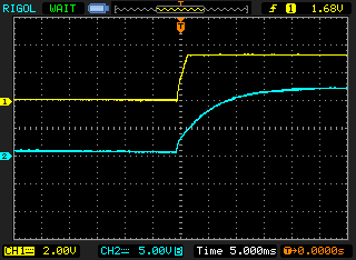 3.3V power up waveform (CH1: 3.3V output, CH2: 12V input, open circuit output) |
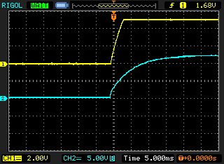 5.0 V power up waveform (CH1: 5.0V output, CH2: 12V input, open circuit output) |
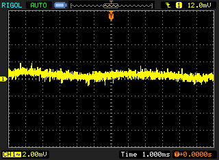 3.3V output ripple (12V input , 275mA load) |
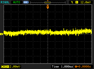 5.0V output ripple (12V input , 350mA load) |
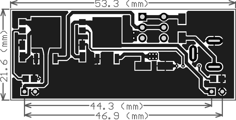
Dimensions
*Note: All tests were performed at 25°C in still air with external heat sink and with only one channel loaded. The maximum current is limited by the power dissipation of the cooling system. I.e. increasing the airflow around the heat sink could improve the current output capability. The maximum current output could be up to 1A with sufficient cooling.