Overview
Compared to semiconductor temperature sensors, thermocouples have a wide working range, and do not need any external excitation power. They are cost effective and interchangeable. In some high temperature application, they may be the only practical choice with a reasonable price. Signal conditioning is the most tricky part for thermocouple temperature sensors, it deals with micro volts amplification and the cold junction compensation. Thanks to the MAX6675/MAX31855, all the signal conditioning had already been done inside the chip, and the amplified analog voltage is digitized and accessible to external MCU via SPI interface.
Features
- 3.3V/5V Powered.
- UEXT Interface
- SPI Interface
Pin Configuration
5-pin 2.54mm Connector:
- MISO: Sensor SPI output
- SS: Sensor SPI slave select input
- SCK: Sensor SPI clock input
- 5V0: 3.3V/5V power supply (VIN)
- GND: Ground
UEXT Connecor:
- Per UEXT definition and pin 1, 2, 9,10 are marked on the PCB, 3.3V only.
Technical Details
To make the sensor work out of box with 5V power supply, there is a LDO regulator serves as a 5V(3.3V) to 3.3V converter, which is as shown in the picture below.
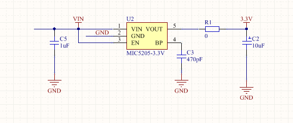
The 5V to 3.3V converting is necessary because unlike the MAX6675, the new MAX31855 could only be powered by 3.0V-3.6V. R1 should be removed to prevent flowing of reverse current, if UEXT interfaced is used.
Below is the schematics for the UEXT and 5-pin 2.54mm connector
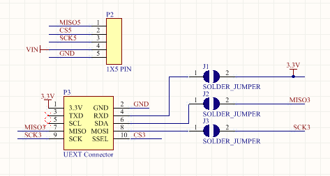
J1, J2 and J3 are used to enable single row layout of the UEXT interface.
Two voltage dividers are used to reduce the 5V level signal to safe 3.3V voltage, as shown in the picture below.
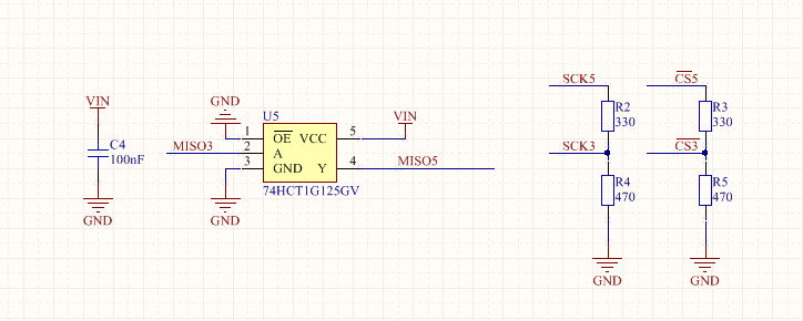
If the module is powered by 3.3V via 5-pin connector, R4 and R5 should be removed to make sure the MAX6675/MAX31855 gets the correct level of voltage. A 74HCT1G125GV buffer, which is powered by VIN to convert MISO to proper level.
MAX6675/MAX31855 and its peripheral components are shown in the picture below.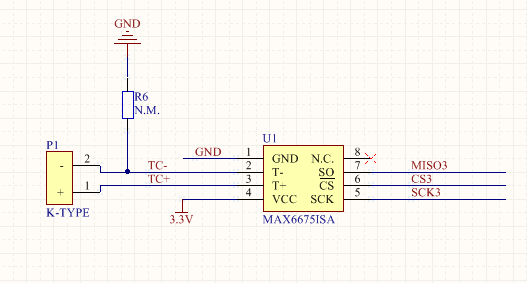
If you are using a isolated thermocouple, you can desolder R6 from PCB.
Resources
- Arduino Library
- MAX6675 Datasheet
- MAX31855 Datasheet
- 74HCT1G125GV Datasheet
- MIC5205 Datasheet
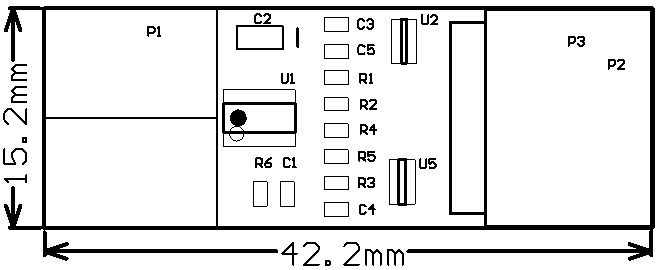
Dimensions
Full schematics is available, please contact us by email.