Contents
Overview
Unlike the chemical CO2 sensor(MG811), this NDIR CO2 sensor does not need a constant ON heating element. The heating element inside a chemical CO2 sensor keeps the sensor warm so that the chemical reaction could happen and produce an continuous EMF as the output, which depends on the CO2 concentration. This NDIR measures the concentration of the CO2 by measure the received IR light strength, it only consume relatively high current during the ON state of the IR emitter. Also, the manufacturer of the sensor claims a ±(50ppm +5%reading value) initial accuracy of this sensor, and it is factory calibrated. According to the datasheet of the sensor, the re-calibration of the sensor is recommended over 6 months of use. The method of the calibration is quite easy compared to the MG811, just put it in fresh air for a couple of minutes and press the “CALI” button on the adapter board or issue a “calibration” command.
NOTE: The USB2.0 port on your PC may not be able to provide sufficient current to power the sensor and your Arduino in the same time. To minimize the supply voltage fluctuation on the sensor, it is recommended to use an external 12V power supply on your Arduino.
Features
- Factory calibrated
- One button re-calibration or via “calibration” command
- Automatic re-calibration over 24-hour cycle
- I2C or UART interface which could be selected by on-board switch
- On-board MOSFET which could be used to turn off the module completely to save power(supported in I2C mode only).
- Configurable 3.3V/5V IO
Pin Configuration
- GND: GND
- VCC: 5V Power Supply
- RX/SDA: Rx input for UART interface or SDA for I2C interface
- TX/SCL: Tx onput for UART interface or SCL for I2C interface
Technical Details
MH-Z16 sensor has a UART interface, and with the help of the adapter(I2C to UART bridge IC SC16IS750) user could connect this sensor to an I2C interface to save two IO pins.
MH-Z16 has a feature called “auto self calibration”, which is an algorithm built-in the firmware of the sensor. The SIMPLIFIED working principle of this algorithm is something like this:
1. The sensor keeps tracking the lowest reading of the sensor since it is powered on.
2. After the first 24hours since it is powered on, it records the lowest value(value A).
3. After the first 48hours since it is powered on, it records the lowest value in the last 24hours(value B).
4. It compares value A and value B, if they matches to some extent, it will use this value as the new baseline value.
5. The sensor repeats 2 and 3 after 4.
The manufacturer claims that the algorithm is effective against long time drift. This feature is good for applications which the sensor will be in fresh air for at least some period of time in a cycle(24hours). For example, in your application, there is always sometime in a day that the CO2 concentration in the room is around 400ppm(theoretically, the CO2 concentration will never below 400ppm in fresh air). However, it is a disaster if the sensor is in an atmosphere where the co2 concentration is always low or above 400ppm(for example,greenhouse).
To “break” the auto-calibration cycle, or to “disable” the auto-calibration, please turn OFF the sensor at least once every 24hours. User could turn ON/OFF the sensor by changing the state SC16IS750’s PIN15 via I2C interface.
PIN16 of the SC16IS750 chip is used as a calibration signal to the sensor, and PIN15 of the chip is connected to a power MOSFET which could be used to switch the sensor ON/OFF. As both the PIN15 and PIN16 is software programmable, the calibration and ON/OFF could be controlled by software via I2C interface. 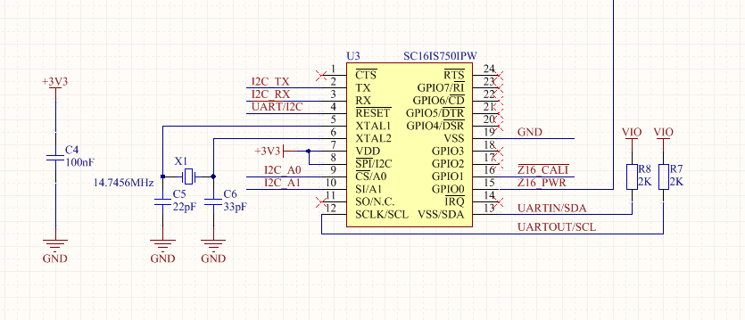
Figure 1: Schematics of the UART – I2C bridge chip
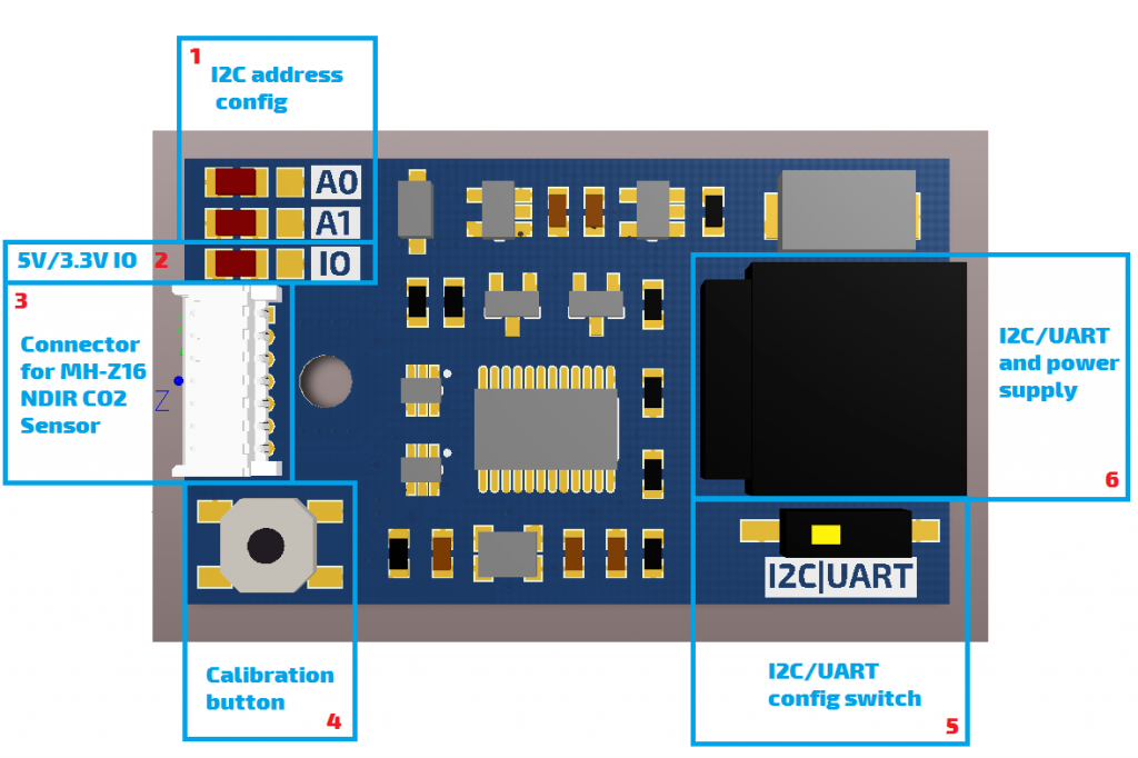
Figure 2: Functions of jumpers, connectors, etc..
The Tx output of MH-Z16 is fed to the SC16IS750 or to the on-board connector,which is selected by a CMOS SPDT switch SGM3157. The same applies to the Rx input of the MH-Z16. An on-board I2C/UART config switch(block 5 in figure 2) select the route of the TX and Rx signals. Slide the stub to the left, the Rx and Tx are routed to SC16IS750, which put the adapter in I2C mode; Slide the stub to the right, the Rx and Tx are routed to the I2C/UART connector, which put the adapter in UART mode.
The I2C address could be configured by block 1 in figure 2. By default, both A0 and A1 are soldered to the left, which means both A0 and A1 are logic “0”. Solder A0 and A1 to right change the logic state to “1”. Table 1 is a table of the possible I2C addresses.
| A0 | A1 | Address |
| Left | Left | 0x9A |
| Left | Right | 0x92 |
| Right | Left | 0x98 |
| Right | Right | 0x90 |
Table 1: Possible I2C addresses
There is another jumper(block 3) next to the two address setting jumpers in figure 2. Connect this jumper to the left, which is the default setting, sets the IO level of the sensor to 5V. Connect it to the right will set the IO level of the sensor to 3.3V.
Re-calibration of the sensor should be done in fresh air. After power on the sensor and put it in fresh air for at least 5 minutes. Either of following method could complete the re-calibration:
- By pressing the calibration button (block 4) for at least 10 seconds
- By issuing a UART calibration command
- By toggle the PIN16 of the I2C-UART bridge chip “LOW” for at least 10 seconds, and then back “HIGH”
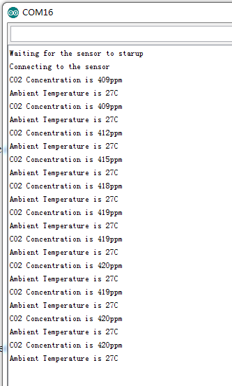
Demo Code Screenshot
Resources
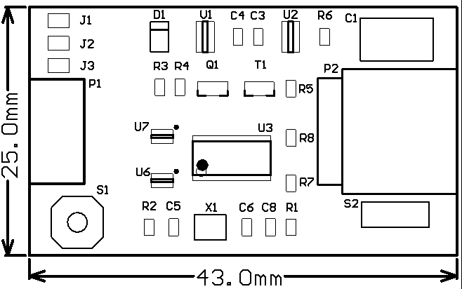
Dimensions
Full schematics is available, please contact us by email.
Hi, The NDIR Sensor is interesting and your website is amazing..
i have some questions to ask, the Z16 calibration pin from sensor probe is not clear enough for me.
what is it function? i know that calibration can be done using the Rx TX pin using some commands right?
will switch S1 trigger the U3, next U3 will send signal/logic to Z16 calibration’s pin and the Z16 do the calibration? is it correct?
Thanks & Regards
Restu
Hi Restu,
Any “low” signal longer than 10 seconds will have the same affect to the sensor compared to the TX/RX calibration command. S1 is directly connected to the calibration pin of the sensor probe, pin 15 of U3 acts as an parallel switch to S1 and pull the pin 15 of U3 to “low” will have the same affect to the sensor probe as you press the S1 button.
Best regards,
Kim
Hi
Where can i turn off the “auto self calibration” algorithm in the code for both modes? (URAC&I2C)
Thank you very much!
Ido
You need to put the sensor in I2C mode(by setting the tiny switch on the adaptor board) to power off the sensor every 24hours and then power it back ON.
https://github.com/SandboxElectronics/NDIRZ16/blob/master/examples/I2CMODE/I2CMODE.ino
Above sketch is for I2C mode operation and there is a function named “power” via which you can control the power to the sensor.
If UART is the only choice in your application, you need to add some circuit by your own to switch ON/OFF the power to the sensor.
Hello, I want use this Sensor in a greenhouse.
Can you please give an example code how to To “break” the auto-calibration cycle, or to “disable” the auto-calibration,
best regards
You need to put the sensor in I2C mode(by setting the tiny switch on the adaptor board) to power off the sensor every 24hours and then power it back ON.
https://github.com/SandboxElectronics/NDIRZ16/blob/master/examples/I2CMODE/I2CMODE.ino
Above sketch is for I2C mode operation and there is a function named “power” via which you can control the power to the sensor.
If UART is the only choice in your application, you need to add some circuit by your own to switch ON/OFF the power to the sensor.
Where can i find the sample code for Raspberry PI? (In Py or Java)
Thanks.