Category Archives: Uncategorized

Seeing is believing. We are selling chips with silicon die shots.

It is not uncommon to see, from time to time, the cries from innocent users that their FT232RL based devices with counterfeit chips are bricked by official driver update. One way to avoid the threat of counterfeits is to purchase from solid vendors, and we want to be one of them. Here are the procedures by which we followed so we can assure that the chips we sell are genuine.

  1. Chips are sourced from vendors who we have been doing business with for years. Some of them are official distributors and some of them are specialized to handle factory surplus.
  2. We visually check each chip to see if they are from the same batch.
  3. We pick 5% percent from the total batch as sampels and decap the epoxy.
  4. We visually check each silicon die of the samples under a microscope to see if they are identical with the known genuine chip.
  5. Seeing is believing. We publish the silicon die shot on the product description page so you can see what is inside the chip and you decide whether to purchase it or not.

Here comes the die shot from 1 sample in 30pcs FT232RL.

IMG_0031 - IMG_0183_6

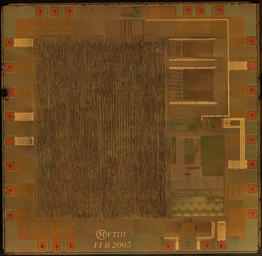
For those who want to see more details please check out our google drive here:

Google drive link

In the link above you can find die shots in the resolution of 18000×17565, 10000×9758, and 5000×4879.

The most high-resolution picture we took for this product is 32597×31810 and it was stitched from 150 pictures took by a SLR. The most high-resolution picture will not be released to the public. if you are interested in it, please submit a contact form.

If you need a cross reference of the die shot, here is the place to go.

This is just a start. If the first batch sells well, we will continue to offer other chips. If you were a victim of counterfeit chips, please feel free to contact us and see what we can offer.

FacebookTwitterGoogle+Share

Brief Introduction to S-Ctrl Framework

Air Series firmware v2.0 introduces an automation control oriented framework S-Ctrl. This framework allows up to 32767 devices to communicate over the 2.4G RF. The network is multiple-access, which means any device could send data to any device, which is similar to Ethernet or WiFi. The framework also defines the messaging format for different automation control purposes.

The Arduino library for S-Ctrl can be downloaded here.  Arduino libraries can be import by clicking “Sketch->Import Library->Add Library” in the Arduino IDE. Detailed instruction on installing Arduino libraries is here. There are basically 2 ways to use this library. The library contains examples in both ways (Raw and Framework).

Continue reading

AirDuino and AirDongle Firmware Upgrade

We are glad to publish v2.0 beta firmware for AirDuino and AirDongle. This is a major upgrade from v1.x. Many improvements has been made to existing functions. An automation control oriented framework S-Ctrl is introduced into this version. This framework allows up to 32767 devices to communicate over the 2.4G RF. The network is multiple-access, which means any device could send data to any device, which is similar to Ethernet or WiFi. The framework also defines the messaging format for different automation control purposes.

This article mainly demonstrates the process of firmware upgrade for AirDuino and AirDongle from v1.x to v2.0. There has been some performance improvements in the RF messaging part. However, compatibility with the 1.x version was sacrificed. This makes the upgrading process complex. The process is not risky, just too many steps to go.

Continue reading

Breaduino- A Breadboard Power Supply with FT232RL USB to Serial Bridge

Overview

With the growing popularity of USB3.0 interface on PC and ubiquity of smart phone chargers, we designed this product with a micro USB connector. When use it as a breadboard power supply, user could power the board via his/her cell phone charger; when use it as a Arduino/USB to Serial Convertor, user just need to plug the USB cable to his/her PC. User could use the onboard config switches to select the operating voltage, crystal frequency of the external MCU. Also, the logic level of the onboard USB to Serial Convertor is 3.3V/5V configurable, too.

Features

  • Seperated 1A rating switches for 3.3V and 5V channel
  • Configurable VIO* 3.3V/5V
  • Configurable auto-reset for Arduino
  • Configurable 8M/16M crystal for Arduino
  • Extra headers to accept female connectors
  • Plug and play design

Continue reading

RasPiDeck Gives Your Raspberry Pi 5V I/O Capability

A few months ago,  Kornel, one of our customers, told us that he wanted something similiar to PiFace. Inspired by this product, I thought that I could make something else which utilizes the shields and sensors designed for Arduino.  There are thousands of different kinds of shields and sensors for Arduino already existing in the market. They are mature in hardware and most of them are provided with open source code.

I told my idea to Kornel and he said the stuff I was going to design is already in the market. However, I decide to design something has more features compared to Cooking Hacks’ Raspberry Pi to Arduino Bridge. I named the product RasPiDeck because it was designed to load  exteral shields or sensors. Here is some features which I think might  be useful or nessessary for RasPiDeck.

  1. It should handle 5V input without any off-board component
  2. It could drive shields/sensors which only accept 5V logic
  3. It must have its own 5V-3.3V LDO, since the LDO on Raspberry Pi is already heavily loaded.
  4. The SPI/I2C interface of RasPiDeck should be able to work on both 3.3V and 5V device.

After a month working(schematics, layout, component sourcing and PCB manufacturing), the first version of RasPiDeck looks like this

raspideck1

It has 19 jumpers on board which are used to select the direction of the header pins,  the logic level of I2C and SPI interface and the source of the referece voltage for onboard ADC.  After my colleague Peng saw this, he said “If I were a newbie, I will be overwhelmed by the jumpers, and it is quite inconvenient to manually config 19 jumpers”  I decided to take his advise and make revision to the first editon.  I was involved in another project which has higher priority after a few days working on the second revision, so after two months the second revision comes true

raspideck2

I replace all the jumpers with SPDT analog switches and add a I2C IO expander to control the switches. Now, it looks less overwhelming and user could use code to config the IO directions/voltage levels and the logic level of I2C and SPI interface.

Below is what it looks like when it sits on a Raspberry Pi,

withraspberry

This product will be handed over to factory next week and it will be ready in about three weeks. As all of our products,  the board color will be blue and the pad will be gold plated. The datasheet will be ready before the product is ready to market and all the technical details will be there.


A bizaare short circuit female header connector

I was fiddling around with a newly designed shield for Arduino and I just can not get the shield to work properly after a few tries.  Then I grabed my DVM and measured power supply pin of one of the ICs on the shield. The shield is supposed to be powered by the 3.3V pin on Arduino.  Superisingly, I found it was 5V!

Then I quickly disconnected the USB cable and pulled off the shield from Arduino.  I measured the 3.3V and 5V pins on the shield. There was no short. Then I measured the 3.3V and 5V pins on the Arduino. There was no short either!!!

I powered the Arduino alone and measured the 3.3V pins, and it gives a good value of 3.35V.

I realized that there may be something wrong with the 6-pin female header of Arduino, and then I tear off the housing of the header and I found there is a weakly contacted solder bridge as shown below:

short-circuit female header 1 short-circuit female header 2

It is a quite old device, I bought it online back in year 2011 or 2010. I had been using this device for years and the symptom shows up today! The problem only happens after a shield is applied to the Arduino.

It seems that the soldering bridge is due to excess solder, excess diameter of the through hole and the unsealed buttom of the header.

This is just another story of how bad soldering affects the long term reliability of an electronics device.